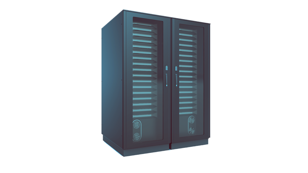
21 Apr Seismic Class Server Racks
Basic principle of design considerations and anchorage for seismic compliance.
In the recent years we had witnessed some of the worst earthquakes and other natural calamity that had caused high level of damage to the public and private properties. Among other essential equipment and facilities, data centers plays important role in maintaining the communications and data exchange during the period of crisis. These is no argument that some of these data centers are extremely vital for the public good and needs highest level of security and protections. There are various levels of safety and security features built around data centers and one such being seismic protection as mandated by various regulatory bodies such as IBC and European Seismic Compliance etc.
What do we mean by Seismic Compliance?
Regulatory bodies of various country have made a set of rules to safeguard the buildings, structures and equipment etc. from seismic vibrations and shocks.These rules are laid in detail and often involves not so easy calculations for the designers. Theses calculations forms the basis of seismic safeguard.
Overview of Data Center Racks –
Data center racks are used to mount various electrical and electronic components which are typically used in digital communication and data support services. Some of the notable components are Servers, Cables, Network Device, Hard Disk, Computer, In-Rack AC and HVAC Ducts etc.

Since we all know that all data center equipment are sized as per U (1U=1.75″). Be it server or AV equipment, they are all made as per U specification. The weight of high performance 2U servers have an average weight of 20 kg (median weight taken from Dell and IBM) with 750 mm depth. These servers are very costly and plays major role in data centers. Typical data center server rack is of a 42U capacity. Hence a full capacity rack will have 840 kg of equipment and approx. 100 kg of cable and accessories and the rack self weight.
Given the massive amount of dead weight that rack holds, it puts a serious liability on the designer to make a near correct approximation in case if anything goes wrong. One relaxation comes from the fact that many times server racks are partially empty for the neat wire and CAT 5/5e/6 fiber optic routing and buffer space for future up-gradation etc.
Understanding the Seismic Disturbance –
The most basic nature of seismic vibrations and shock is observed in form of horizontal lateral movement. These horizontal movements are quantified in terms of acceleration “g”. The acceleration passes underneath the structure/building/equipment base and exerts maximum force which is called as ‘horizontal base shear’. US Geological Survey ( https://earthquake.usgs.gov/ ) maintains a great volume of literature and ongoing scientific findings in this area. The important factor for seismic consideration is the geographical area where the rack is placed, soil characteristics of the area and perceived level of hazard the rack poses in case of accidents. Based on these information the seismic data is taken from the past record based on the spectral response in terms of “g”.
Anchorage –
Along with spectral response and perceived risk the “Seismic Design Category” is assigned to the rack assembly. This design category will form the basis of design calculation and compliance summary in terms of anchorage of the rack assembly to the concrete foundation.

Before we discuss the anchorage, we need to analyse the correlation of spectral distribution of seismic vibration and the fundamental period of the structure/racks. To make it even more simpler, when the base soil vibrates it induces disturbance on to civil structures and makes it vibrate and hence any equipment/rack/items inside the structure starts vibrating.
The above simulation highlights the detriment of horizontal base shear on rack assembly. It is evident from the simulation that both shear force and moment acts simultaneously. There are two factors to be considered, one is the analysis fundamental period of rack assembly in relation to the ground response and other is the design spectral response to be deduced for considering the anchorage. In a simple word, the interaction effect of vibration response of ground surface, buildings and rack assembly has to be deduced in order to comply the anchorage.
Notably two failure safeguards are necessary, one is the steel bolt failure and other is the concrete failure. Concrete design is done in accordance with the “Kappa Method”. Concrete is susceptible to brittle failure in many ways and needs extra care in design analysis and if possible a test model should be prepared for more reliability. Bolts follow general design criteria for the given load as tensile and shear being dominant.
Vibration Isolation –
Vibration isolation is sometime mandatory where a constant vibration disturbance is induced in the buildings/racks through mechanical or electrical equipment placed nearby and has a significant amount of transmittance.

Bayed rack system provides great benefit in saving space and improving HVAC or CRAC efficiency. In addition to that they are sometime placed on vibration isolator to provide extra rigidity and rack stability during seismic shocks.
The calculation summary has not been included due to the fact that they are lengthy and involves detail summary of the load case and seismic history from USGS. Hence, they are left for the readers to go through the compliance summary and follow as required.
Referance:
1. IBC2015
2. ICBO
3.USGS
4. NCEER Technical Report
5. ASCE


ปั้มไลค์
Posted at 16:28h, 12 JulyLike!! I blog quite often and I genuinely thank you for your information. The article has truly peaked my interest.